 |
||
|
What happens without a tail? If you have a wooden model of a plane, I would not advise to rip off the
tail. If you throw the model without tail, it will dive to the ground.
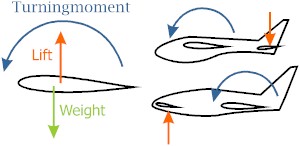
Why? Every airfoil has three forces. Lift, weight (both vertical) and drag
(horizontal). If lift and weight are placed on the same spot, the airfoil
is stable. But most airfoils are not stable. The lift force is mostly
located after the weight force. So it generates a turning moment. This
turning moment is compensated with the down pushing force of the
horizontal tail surfaces.
|
|
|
|
A canard has an upward force in the horizontal
"tail"-surfaces. Flying
wings, why? Every plane (with a tail) also has a long fuselage to fix the tail to.
This fuselage and tail create extra drag. Performance gets less due to
this drag. Many designers came to the thought: "why not delete the
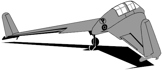
fuselage and the tail". Flying wings were born. The name flying wing is not totally correct. Most
full-scale designs still have some sort of fuselage. The Horten-brothers
and Northrop made (to my idea) the only pure flying wings. The Horten IX
V2 (1945) and the B-2 (1990’s) have proven that the concept can be
achieved. Other designs have fuselages and fall under the name
"tailless airplanes". But some still have vertical tail
surfaces. So… we make it ourselves simple and call them all "flying
wings". |
||
|
How flying without tail? There are four ways when using a rigid wing (not a pure textile wing like
a parasail).
What is achieved by using sweep and twist? Well, the tips provide the
compensating down- (in case of backward sweep) force or up- (in case of
forward sweep) force to the turning moment of the airfoil in the center.
|
||
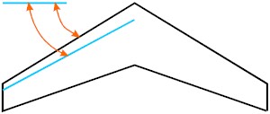
The angle of sweep can be shown in two ways. One
is to the leading edge (used by Horten), the other is to a line, which is
placed on 1/4 of the wing. Make sure, when using data of exciting models,
that you don't use the wrong angle. If not mentioned which angle they use,
take the one to the 1/4-line.
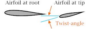
The twist-angle is the angle between the airfoil at the root of the wing (nearest to the fuselage) and the airfoil at the tip of the wing.
|
||
|
Advantages:
Disadvantages:
|
||
|
||
|
||
|
Designs
using auto stable airfoils
(also
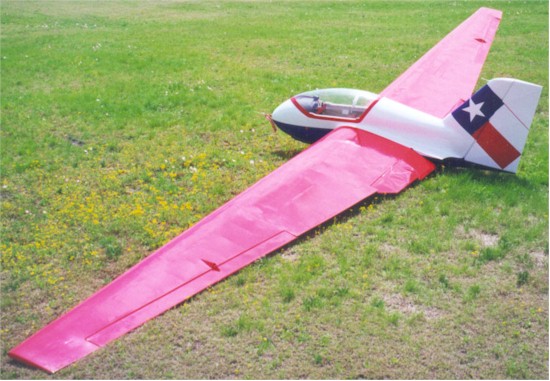
called unswepted flying wings) These designs use an airfoil, which doesn’t require a sweep. Therefore
they are the most compact version of a flying wing. Fauvel, a French
designer, became famous with his unswepted designs. These designs are
without vertical tail very unstable, so most designs have a vertical tail. |
||
This airfoil (CJ-5) is an example of an auto
stable or reflexed airfoil. Note that the trailing edge goes up. You can see
a reflexed airfoil as a normal airfoil with a tail-airfoil in one.
|
||
|
||
|
||
|
Advantages:
Disadvantages:
This concept is, according to some people, not a true flying wing. Euh...
I don't see a classic tail, or a canard, so I see it as a flying wing. What has happened in this concept? The wing has a great angle of sweep (a
German design had 40°). The classic horizontal tail surfaces are placed
on the tips of the wing. This way you have the necessary down force to
compensate the turning moment of the wing (the force-arm (distance between
center of gravity and elevators) is long enough) and you don't need to
have a long fuselage to hold the tail. Most known designs have the
vertical tail also placed on the tip. Here you can also combine the
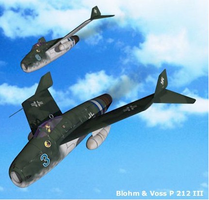
elevators with the roll-rudders (combination known as elevons). The German company Blohm & Voss did some tail-on-tip-designs in WW
II. The Luft '46-site (see links nurflugel-site) has many of the
unfinished projects of the Luftwaffe. They have superb 3D-drawings of some
of these designs.
|
||
|
||
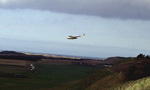
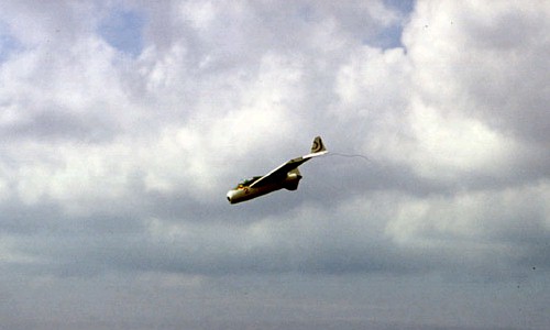
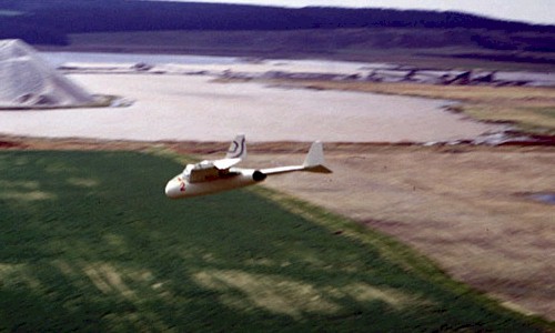
| I got these
pictures from Bjorn Rabben. They show his model of the Blohm & Voss P212. He did use
elevons in the main wing instead of the original rudder configuration. Click the thumbnails to see the larger pictures. |
||
   |
||
Advantage:
Disadvantages:
|
||
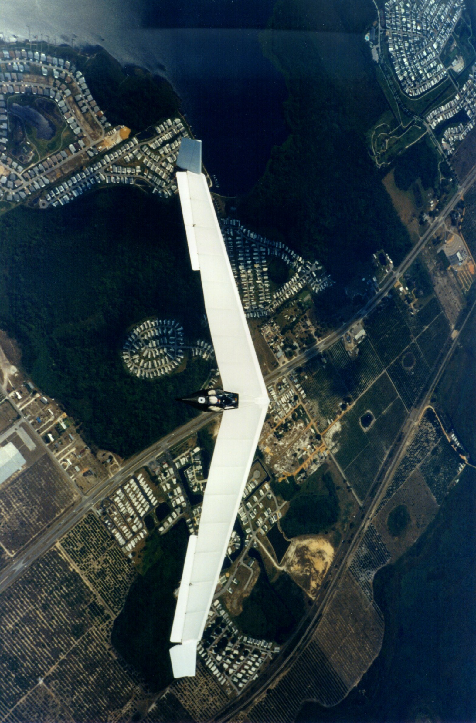
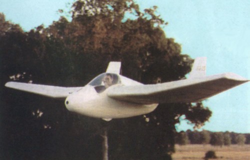
| Low CG The moment created by the wing gets (fully or partially) compensated by
the very low CG. This technique is often used with ultra light. Mostly
hang gliders (using weight shift as flight control) use this technique to
its full use. "Mitchell
used this technique for his B-10 flying wing ultra light." This quote
from an Air Enthusiast edition probably mentioned that if the cockpit
would be higher placed, that the control surfaces needed to be larger to
control the airplane. The newer U-2 of Mitchell has a higher placed
cockpit, but it also has a longer force arm between the CG and the control
areas (the B-10 has a straight wing, while the U-2 has some back sweep).
Both airplanes use the low CG technique partially. Flight control is done
by control areas hung under the trailing edge of the wing. Advantages:
Disadvantages:
|
||