 |
||||||||||||||||||||||||||||
|
||||||||||||||||||||||||||||
He got his inspiration after seeing the Westland P12 "Duo-Mono". This plane, which was a conventional airplane with a large tail, have the possibility to place the center of gravity (CG) more backwards. It wasn't a tandem, but that idea began to get shaped in Miles' brain. Persons who now think "Hey, it was a Frenchman who made the first tandem" need to read further. Mignet is also included in this page. He is one of my favorite airplane designers. He thought about his little, but remarkable airplane AND about the people who wanted to build it. Great man. Love him. :)
I found in Air Enthusiast / number five (a magazine) the following list of advantages Miles thought to create with his tandem.
This may sound like Chinese to some. So, let us review the lines.
|
||||||||||||||||||||||||||||
An aircraft that can still maneouver at low speeds while it's opponent cannot, may well win out in a turning fight). As to landings, increased Ci can also decrease the nose-up attitude during landings, making the runway/carrier deck more easily visible to the pilot. The US Navy made a hybrid out of this concept in the F-8 Crusader, by tilting the wing several degrees during landing to allow the pilot to remain almost level during the approach, thus allowing him a better view of the carrier deck then would have been possible otherwise given the high stalling speed of the aircraft. I got another remark about maneuverability by Evan L. Mayerle. It is not Cl related, but interesting to know anyhow. A: "Well, first of all, concentrating all your heavy items, like the engine, near the cg is going to reduce your moments of inertia so that a given input will get more output. By the same token, splitting the lift between two wings, especially if the split can be controlled or varied, can also enhance maneuvarability. I don't think that an increased Cl can, of itself, increase maneuverability; however, it's been decades since I took any Aero. classes and my work has been mostly detail design, not overall configuration." The time when I did receive this mail the text above was not yet placed. So he could not have known about the relation J.T. Wenting mentioned.
|
||||||||||||||||||||||||||||
|
||||||||||||||||||||||||||||
|
||||||||||||||||||||||||||||
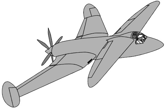
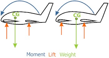
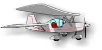
Here two situations can be seen. First the cruising condition, second the tandem during landing while using a higher angle of attack. The lift forces have shifted backwards. The rear wing lift force is further away from the CG and generates a larger moment than while cruising. The first wing lift force is closer to the CG and has to be larger to compensate the moments. But anyway, here with tandems we use LIFT. Conventional airplanes have to use more downwards pushing force at the tail. George Miles was very, very enthusiast about this tandem idea. Seeing his advantages, who wouldn't be? But would the plane be stable? He still had to prove. Miles knew this and made a proof-of-concept airplane to get support for his Fleet fighter proposal. He made the M 35 in 1942 as a private venture without the knowledge of the Ministry of Aircraft Production. Roll-out was at the end of April 1942 after only 6 weeks from the start of the build up. This was possible due to the extensive use of existing parts (NASA today uses this strategy as much as possible when making their X-planes). |
||||||||||||||||||||||||||||
|
||||||||||||||||||||||||||||
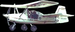
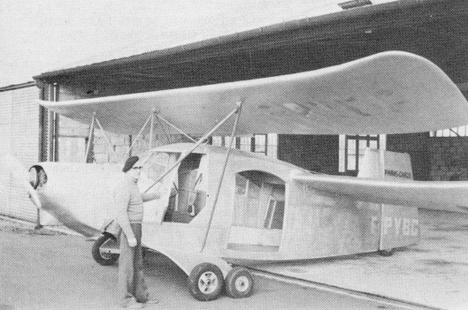
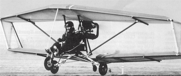
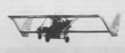
Miles M 35. A proof of concept airplane. Build in six weeks. Miles flew the plane himself on its flight
flight. It nearly ended in disaster. It was very unstable around its pitch axis. Even
after ballasting, which improved stability, the overall result was still not so good. But
Miles thought it had proven his idea. Windtunnel tests would have showed this instability,
but I guess Miles was in a hurry. |
||||||||||||||||||||||||||||
|
||||||||||||||||||||||||||||
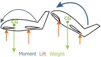
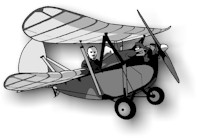
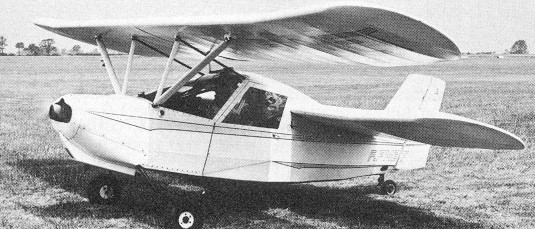
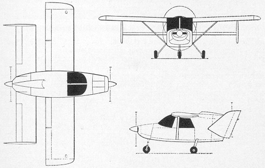
Miles M 39 B with its unusual engine configuration. After viewing the M39B the Ministry got interested in the tandem design and bought the plane to test it. Now let us see the situation. We have two wings. How would you position
the control surfaces? ... Miles did it as following: flaps on both wings, elevators on the
front wing, ailerons on the rear wing and rudders at the wingtips and there also was a
non-moving tail at the end of the fuselage. Elevators and ailerons were positioned next to
the flaps, which were placed next to the fuselage. But the thing that interested the Ministry was
its stall behavior. You couldn't stall the M39B if the flaps were placed in its neutral
position. The Ministry asked more tests to explore this non-stall behavior. Pilots founds
out that it got lost when flaps were being used. It was even so that if the M39B stalled,
it happened without warning! So it was good news and bad news. Later more about the good
news (when talking about the designs of Henri Mignet). The M39B was a scaled down version of the bomber proposal of Miles. So it wasn't stressed for acrobatics. On one of the flight a pilot encountered some turbulence. He later said it felt like the cockpit wanted to break off. It will not be a surprise if I tell you that there were no orders for the M39. In fact, the whole specification B.11/41 lapsed. This story of a "new" (see later)
concept, which didn't get orders but was build twice without official support, shows that
a designer can sometimes be so enthusiast about his proposal, that he is blinded from the
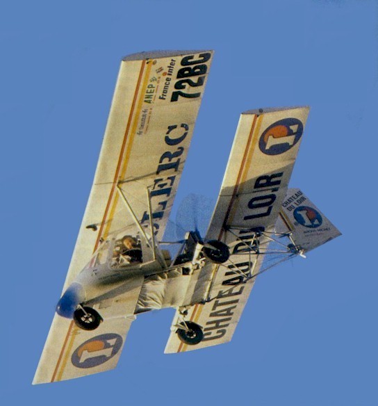
fact that there is still a lot of work on the design. You might think now that the tandem concept isn't worth a penny. Well, you are wrong. There are several successful tandems out there. Best known is the "Pou de Ciel" (Flying Flea) of Henri Mignet. To my knowledge the first tandem was the "Pou de Ciel" (1933) of the Frenchman Henri Mignet. It was his fourteenth design. That's why it did received the designation HM-14. Compared to the design of Miles you can see the following differences. The HM 14's front wing is larger than the rear wing. The horizontal distance between both wings is smaller. The single vertical is placed on the fuselages end. The pilot is positioned between the wings. A classic landing gear is used. The front wing does not have elevators, but the whole wing rotates. The engine was placed in the front.
Using this configuration it made Mignet possible to create a compact, light, cheap, easy to build airplane. A real airplane for "the man of the street". At the same time Henri Mignet wrote his book "Le sport de L' Air". This book also contained the plans to build a HM-14. The English translation sold over 6000 copies! Soon there was a real Flea fever. About 600 Flying Fleas were built. All went well.. but then came the crashes. Several HM-14 fell out of the sky. The accidents were caused by some design mistakes. Mignet placed the pilot behind the center of gravity (CG) and if a lighter pilot (Mignet being a bit heavier than the common person) flew the airplane the nose couldn't be kept up after a dive of 15�. Several pilots dove to their death. Mignet quickly redesigned the HM-14 in 1936 a controllable rear wing. Mignet created a nose-up with this control. You can see the problem Henri Mignet had in one of the drawings above (the one about shifting lift forces). In that drawing you see that the lift forces can shift backwards. If they do you need to have enough weight behind the CG to have a good chance to counter this moment with the front wing. If the front wing has limited rotation and the weight behind the CG is less than the design weight ... you have lost of problems. The newly controllable rear wing rotated automatically to a lesser angle of attack if the stick was pulled to its extremes. This way the rear wing creates less lift and the moment around the CG gets smaller. The lift of the front wing will now be large enough to counter the moment around the CG and prevent the unstoppable diving, which killed several. The system worked. But already many countries grounded the Flying Fleas. And quickly the Flea fever died. But this didn't stop Mignet. He kept designing tandems. I quote the book "The design of the aeroplane" by Darrol Stinton. He gives a good and complete view on the possible mistakes in the HM-14 design and how they were solved. "Four factors appear to have contributed to the HM-14 accidents, and they are worth recounting:
There is also evidence from later variants that the control power of the foreplane is affected by propeller diameter. ......... A tip that is not high as the foreplane can cause a reversal of circulation beneath the centre section when power is applied, making it harder to lift the nose. A propeller should be about 4 in (10 cm) higher than the foreplane to maintain the authority of the control in pitch. Althoough Flying Flea variants can fly with quite low power engines, the small propellers used with such engines on gyrocopters, for example, should be avoided at all costs.
Mignet's wingarrangement was close to that of a biplane with considerable stagger and a small gap. Or both wings could be taken as a single low aspect ratio wing, incorparating a slot, in which case aspect ratios varied between 3.3 and 3.43 depending upon the span of the foreplane. Zimmerman showed in 1932 that wings of very low aspect ratio have effective spans about 5 per cent longer than the actual span because of the closeness of the tip vortices, which dominate the aerodynamic picture. .............. It is possible that the unusual, but effective, flying characteristics of the Flying Flea owe something to the phenomenon." One could rephrase the last chapter by saying that most problems were gone by the use of autostable airfoils. These airfoils have a lift force which doesn't move (too much) when having a larger incidence angle. So there is no more problem with lift forces shifting backwards and increasing the moment around the CG. The moment can no longer go crazy like in the earlier HM-14. Paul Pontois, a known name in the Pou world, writes that a Pou du Ciel with a tested AUTOSTABLE airfoil, enough frontwing rotation angle (no negative incidence!) and a good positioned CG does not need a Cosandey flap. I found a picture of a glider of Louis Cosandey. The glider had a flap on the rear wing. It was probably used only to move upwards to reduce the lift force of the rear wing and to reduce the moment that killed several pilots. It is my opinion that the rotating rear wing of Henri Mignet had the same function. So if Paul Pontois says that a Cosandey flap is not needed in his named conditions, a rotating rear wing is not needed too. I found some info about the
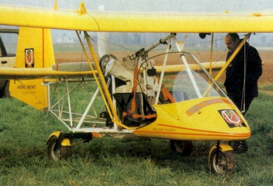
HM 1000
"Balerit", a very popular ultra light two seater (empty weight 174 kg (383 lbs).
It is based on the same configuration as the HM-14, but it is not comparable
in use (foldable wings and without trailer transportable behind a car). I am not sure that this one is designed by Henri, it could be done by a son. Kruhmin
Nikolas did confirm this thought. |
||||||||||||||||||||||||||||
|
||||||||||||||||||||||||||||
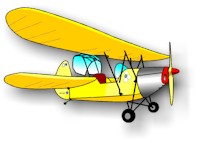
The Mignet HM 1000 Balerit, a later development of the first "Pou de Ciel" |
||||||||||||||||||||||||||||
|
||||||||||||||||||||||||||||
Sure is a eye-catcher this HM 1000 Balerit. Like most Mignet designs it has two controlled axis (no ailerons). And I noticed that there is no longer a flap on the rear wing. So I guess that the designer placed the pilots (seated next to each other) on top of the CG. After this bit of history, let's look at the design of the HM 1000. It doesn't stall either. We sure need to look deeper into this item. Here the elevators are placed in the wing, which stalls first. When stall occurs, the elevator can not longer keep the nose up. So, the nose drops lightly. As soon as the elevator gets lift again, the elevator works again and the nose rises again. This doesn't lead to a stall with a severe height loss, but to a controllable (but steeper than normal) descent in a wave shape. And that sounds rather safe to me for a beginner pilot ( and all the others). Marske uses this system as well on his flying wings. Go see his designs at www.continuo.com/marske. His flying wings stall first at the section next to the fuselage. Now guess what is located in that section. Right,... the elevators! Now let's see the other design features on the HM 1000. Miles choose for a larger rear wing, Mignet for a larger front wing. What is the advantage of Mignets choice? Well, here I have no books or articles about. So, let's use logic. Miles designs had a CG, which was placed nearer to the rear. Mignets CG is placed more to the front. This fact influences the placement of the rudder. Miles couldn't place his moving rudder on the end of the fuselage. It wouldn't be effective enough. He had to place the rudders at the wingtips (the rudder on the end of the fuselage wasn't a moving one). Mignet placed his rudder a bit after the rear wing. The distance between rudder and CG is larger and will be mor effective. I guess it does take less extra weight than the reinforcement needed to place the rudders on the wingtips. Anyhow, the distance between rudder and CG will be smaller on a tandem than on a conventional airplane. So, a tandem will always have a larger tail. The Quicky is a exception. The designer did make the fuselage longer and placed a normal tail.
|
||||||||||||||||||||||||||||
|
||||||||||||||||||||||||||||
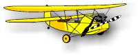
Here you can see the basic differences between a tandem with a larger
first wing and a tandem with a larger rear wing. The place of the CG is different and the
distance between the CG and the tail is different. The distance between both wings is smaller in Mignets design in relation to the Libellula. The consequences of this decision are positive and negative. Positive news is that the design is very compact and very light. Like a testpilot mentioned before, Miles had problems with the fuselage of the Libellula. His fuselage should be made heavier to hold the high lift forces, which are placed further away of each other. If a tandem would be made with a looong and light fuselage and a large distance between both wings, it could snap in two on the first turbulence. Negative news is that, if the distance between the wings is short, the distance between CG and the elevator is also short. So you would need more deflection of the elevator to steer the airplane around its pitch-axis. Trim drag becomes high. High performance will not be possible in this configuration. But it makes a good configuration for a cheap, light, compact airplane. The sales of Mignets prove it! Oh yes, I nearly forgot. The HM 1000 has a very unusual place for its single propeller. It is placed between both wings. It makes a centered weight position (by placing the engine near the center) possible. |
||||||||||||||||||||||||||||
|
||||||||||||||||||||||||||||
The HM 1000 Balerit did prove his value in several events. By some luck I ran into the official site of the Mignet-plant. It is http://avions.mignet.free.fr/ . I did see for the first time that there is a more advanced version of the Balerit, the Cordouan. It has a enclosed cockpit now, which also was a option on the Balerit, but here there is no longer a main tube frame. You could call it a fully "traditional" version of a tandem. It has a remarkable new feature. The front wing is a "floating wing". I do mean that it is only attached at the usual front attachments. The usual Mignet control rods to the rear of the front wing are gone. In earlier Mignets these control rods pushed the wing up or pulled it down to control the pitch. Now there is some kind of flap installed in the front wing which increases or decreases the angle of the wing and so controls the pitch. Mignet claims it has a stabilizing effect during wind gusts. Once I know more about this system I will place it in this page. |
||||||||||||||||||||||||||||
|
|
 |
|||||||||||||||||||||||||||
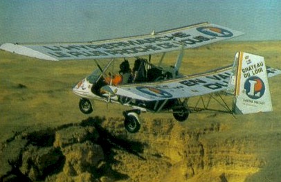
The Mignet Cordouan, the advanced version of the Balerit. If you like to know more about the Mignet, please contact the Mignet-plant at avions.mignet@free.fr In the links page there are several sites mentioned dedicated to the "Pou du Ciel" or "Flying Flea". One of my favorites is pou.guide.free.fr, a French "encyclopedia" about the Pou du Ciel. There is a newsletter about Flying Fleas. It is called "Pou Renew". You can get it on http://www.flyingflea.org. The site itself is worth visiting too. It has a wonderful text (in English!) about how the HM-8 and the HM-14 was developed. Excellent reading! There are other designs which have their origin in the plans of Henri Mignet. Some are variations of Henri Mignets plans to update them to new materials, new use, new airfoils and so.
There are other tandems, of course. Several are very close to the configuration of the designs of Henri Mignet. I just mention a few.
There are several other designs with tandem configuration. I found a few in the ultralight aviation. One of them is the Sunny. It is a boxed wing tandem ultralight. Due to the fact it is a boxed wing it is a very rigid aircraft. Here you can see the prototype. Later it got a open fuselage.
Another ultralight is the Gull. The only data I have on this one is a small, unclear picture and the fact that it was distributed by Eartstar Aircraft Inc. I read "Both the Ultra Gull Deluxe and the Laughing Gull come equipped with three-axis controls, main wheel brakes, double surfaced wings, shock-absorbing landing gear, 4130 Chromoly steel/enclosed fuselage and steerable nosewheel. Earthstar Aircraft Inc., Star Route Box 313, Santa Margarita, Calif. 93453 (805) 438-5235" (quote from "Homebuilt aircraft", febr. 1986). You can see that the wings have the same span (well, that is what I think to see on the picture). The connection between both wings should enhance the rigidity of the design. But I have no clue about its stability.
Like you can see, the Pou hasn't lost his followers. And you will be convinced that there will be a new revival of the Pou in the USA, when reading the stuff on www.flyingflea.org . In France, the revival began a lot earlier. But that will be not hard to understand when you see the several French designs you can find. We (Dutch spoken people in Belgium) have a saying "Geen sant in eigen land", which means "No saint in own country". I am sure that many designers or whatever have become victim of this saying. Mignet sure wasn't. The Mignet firm is still very active in France. I found several articles which might give a better insight in the theory about tandems. I was lucky to find these because it showed me that I made several errors myself in my sketches. Many amateurs like me will fall in the same mistakes. So here I go trying to prevent you making the same mistakes. First you need to know a bit about downwash. In short: air flows over a wing, but after the wing there is a section where the air is going a bit downwards. Wings placed in this section don't use the incidence angle they are been given by design. The reason: the air over the second wing is not coming at the same angle towards the wing as they do with the first wing. The second wing has less incidence, due to the fact that the air going to the second wing is angled downwards. What is the consequence of this phenomenon? Well, the error in my sketches was that I drew the AC (aerodynamic center) of each wing (Mignet wings are straight wings, here the AC of each wing is at 25% of the chord), measured the distance between them and placed the total AC (both wings together) at a relative distance related to the ratio between the surfaces of both wings. Imagine that the front wing is double the area of the rear wing, so the rear wing is 1/3 of the total area. My AC total was placed at 1/3 of the distance between the ACs beginning from the front wing AC. That would have been right if there was no downwash. Due to the downwash both wings may not be treated equal. The rear wing is generating less lift. So the AC lies before the point I drew. The CG (center of gravity) should be placed a bit in front of the AC total as in each airplane. If you use the dimensions of the HM-290, a later model than the HM-14, you should place the CG at 23% between the ACs. Just make a quick sketch of this model and compare the place I thought to use with the place it should have been.
If you want to experiment with tandems you could use the following formula (I found it in a article written by Phillippe Balligand, a designer who made several tandems. It was placed in the site pouduciel.decollage.org . The site is in French. So is the formula.
XF= distance between reference
point (leading edge of front wing) and AC total If you know aerodynamics better than I do, you might be able to use this formula. Only one remark: the author mentions not to forget to keep in mind the downwash. You can do this by reducing the coefficient dCar/d(alpha) by about the half of dCav/d(alpha). Airfoils, aspect ratio and so are not taken into consideration. Another article I found mentions a easier to understand description of the stability in pitch of tandems. Above you could see that the CG is placed more to the front than first thought. With other words ... the weight is nearer the front wing than usual. It makes that the wing loading (kg/m2 or lbs/sq ft) of the front wing is much higher than the wing loading of the rear wing. In the theory section you can find that the wing loading is in relation to the needed speed to keep a wing in the air. Both wings will always have the same speed. You are in big trouble if they are not! But the limit of the first wing will be reached sooner that the limit of the rear wing. So the front wing stalls a bit, drops, gains due to the increased speed lift again and this will continue till the pilot alters the situation (increasing power, flying at lesser angle of attack). The Mignets are known for their parachute-like descent. You can not stall the plane... it just starts to descent faster but still under complete control. Man, I just read the english
translation of "Sport de l' air" (the book of Henri Mignet)
(edition
1934). I
found it at www.flyingflea.org.
This sure gives a true insight in the problems Henri Mignet encountered in
his search for the perfect airplane for the man of the street. One thing I
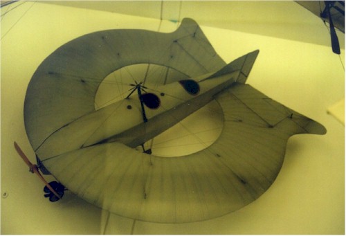
can tell you in short. In the same book I found out why Henri Mignet choose for two control directions instead of the classic three. In classic airplanes you get a lot of shouts from your teacher if you cross the controls (stick left, rudder (feet) left). No wonder they yell. You could enter a spin. Bad for your health if not knowing how to counter it. Well you only have one stick and no feet controls, you no longer can cross controls. Another brilliant idea. You probably now wonder "but can a airplane still turn only using two direction controls?". Yep, it can. I experienced in myself with the only model I flew. The use of a rudder can make you roll. I even did rolls with my trainer remote control model. OK, they were not rolls in one line. It was a barrel roll. Just like the airplane would roll if you put a very large barrel above its wings and you let the airplane slide over the barrel to the top and back down the other side. Every remote control model pilot knows that you can fly with just two controls. Most of them have learnt it that way. Well, Henri Mignet must have thought that beginner pilots should learn it this way when stepping in a full scale airplane. I truely understand this point of view. I am looking forward to my own flights with a Pou-du-Ciel. I hope to learn to fly using a hangglider in the Pou-du-Ciel formula, a Butterfly #01. Ringwings are something weird, but I think of them as tandems. In the Science Museum in London I found a model of one of the annular experiments of Lee-Richards in 1911-1914. It looks like a flying pancake but with a hole in the middle. A fuselage crosses the hole. The wing is supported by a bunch of cables. The model only shows elevators and a rudder. There are no ailerons. Or were the elevators mixed with ailerons?
|
||||||||||||||||||||||||||||
|
||||||||||||||||||||||||||||
| Another
interesting ringwing was the Pusher of Ben E. Brown, it had a highwing ringwing and a wing
as strut. The highwing didn’t had a circular shape, it was more a kind of diamond
shape. One could say that it wasn’t a tandem because it has three wings. OK, but the
basic system will be the same. That's why I did place it here. The Ben Brown Pusher had a prop at the rear, it was driven by a extension shaft. You could consider the placement of the elevators as a classic control surface version of a Mignet "Poud de Ciel", because the elevators are placed on the forward wing. They are placed just next to the fuselage so the force-arm length became as large as possible in this configuration. Placing them at the rear wing would increase the force-arm length, but you would loose the stall free character of the airplane. Serge Krauss have me the number of the US patent of the Ben Brown Pusher. It is 1.836.896. It was filed on 7 July 1930 and it was granted on 15 Decembre 1931. |
||||||||||||||||||||||||||||
The pusher of Ben E. Brown In the August 2001 edition of the magazine Kitplanes I found a article by Howard Levy about the Orbit Air of David Meyers of New London, Wisconsin. It is a double ringwing. Euh... how explain without picture? Euh... when seen from above it is a ring. When seen from the front it is a ring too. Just like a cylinder lying on its side and its sides being pulled one before the other. David Meyers is still working on his design which he patented in 1991. The first version had a forward lower wing and was a glider. Later he changed his configuration into a lower rear wing which now has a 40 hp engine. David Meyers mentions in the article that the airplane was designed with strength, stability and safety in mind. I want to get in contact with David Meyers. I believe he is or was a EAA-member. I want to understand better why he designed his Orbit Air this way and I might have some ideas he could use. Like almost always my ideas come for free.
|
||||||||||||||||||||||||||||