 |
||||||||||||||||||||||||||||||||||||||||||||||||
I know that a on-line program to estimate the performance of a design can be usefull to learn more about airplane-design and it could help several beginners with their first steps into aviation and its design. I still have some questions about the theory. If you can help me, pleeeaase, take contact with me and help us to get started. I will mostly use two books as guidance. One is a translation of a paper of Stelio Frati about gliderdesign. The other is a work of a Dutch engineer who give classes in a airplane-design-school. It covers a lot about motorized airplane design. I have a lot of formulas to use. I understand a lot already, but I miss some knowledge. Pleeaase, help us. The time is limited. The kid of the father will be going to school in 2003. I guess that I might loose contact with the (JAVA-wiz) father. More theory Changing the size Everybody dreams of having a replica of some famous airplane. Mustang,
Corsair, Fw-190, Mosquito would be just a few on the most wanted list. But
I need to warn those who want to make a scaled version. Imagine you would
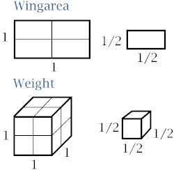
like to make a 1/2 scale version of a Corsair. The wing area and the
weight will be less than the original, of course. But the wing area
will be 1/4 of the original (1/2 . 1/2= 1/4), while the weight will be 1/8
of the original (1/2 . 1/2 . 1/2= 1/8).
Here
you can see that wing area uses two dimensions and weight uses three
dimensions. That's why the relation wingarea /weight changes when scaling
an airplane. What are the consequences of these changes in the relation wing area /
weight? Well, we need to look at two different situations. First we look
at scales larger than 1 (bigger than original). Here the weight rises
quicker than the wingarea. This situation leads to larger wing loadings
and all its problems (underpowered, high stall speeds, clumsy steering).
Secondly we look at scales smaller than 1 (smaller than original). Now we
need to look at two different phenomenons. The first is related to what we
told you here above. The weight drops quicker than the wing area. This
leads to low wing loadings. These planes are livelier than the original.
This sounds like fun. But remember that some WW II-airplanes were so
lively and agile that they became deadly. Imagine a scale down version of
such an airplane in the hands of a beginning pilot. Aaaaaah! Secondly you
need to know that scaling an airplane doesn't scale the surrounding air.
When using slow wings you need to keep this phenomenon in mind. What
happens? An airfoil, which performs very well in a WW II-airplane, can
perform less if you scale the airfoil to a hand throw model. What happens
around the airfoil? The air around the airfoil separates quicker. You can
avoid this situation by choosing an airfoil that is less thick. The
Reynolds-number range of an airfoil can help you in your choice of
airfoil.
This can be simplified to:
Using the smallest chord and the slowest speed you will get the lowest
Reynolds number the airfoil has to have. There are many lists on the net
where you can find airfoils and their Reynolds number range. Be sure not
to forget to check the airfoil when starting a new design. If you use an
improper airfoil, you may get stalls earlier than expected and this
mistake can be deadly to your model (and/or the pilot). Also keep in mind that the performance of an airfoil depends of the used
Reynolds number. A certain airfoil has a higher maximum Cl when
used with larger chords. Remember: larger chords lead to larger Reynolds
numbers. When using a smaller airfoil (like RC (=Radio Controlled)
-models) the Reynolds- numbers is much lower than when using the airfoil
for a full-scale, piloted airplane. So don't use data (like maximum Cl,
minimum drag) of an airfoil when they are generated at lower or
higher Reynolds numbers. A deadly mistake! Changing (or choosing) the airfoil This choice can be difficult, because the choice is enormous. You need to
keep several things in mind while choosing an airfoil. First, the Reynolds
number. Make sure your situation is located in the Reynolds number range
of the airfoil. Secondly, the lift/drag relation. Every airfoil has his
typical curve. We will help you in understanding these curves. The
polar
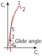
A example of a polar Several, easy to be found points on the curve can be of
great importance to you. Point 1 (Cl max) is
easy to find. That's the point on the top of the curve. At this point you
can calculate the stall speed. Put Cl max into a variant of
formula 1 in formula 2 (see The
forces) and you get:
Point 2
shows the stall of the airfoil. Do not make the mistake by using this
point to calculate the stall speed. You really need to use Cl max
for that issue. Point 3 is the point with the lowest Cd
value. That's the point on the left on the curve. At this point you get
the highest speed. Point 4 is the point where the curve
crosses the X-axis. Here is the point for a dive. Every point below the
X-axis is related to inverted flight. Theoretical
glide ratio You could already read that finding the glide ratio could be easy to
find. It is simply the smallest angle possible between the Y-axis and the
line constructed between the origin (point 0,0) and a point on the polar
curve. But a simple polar does not contain all the factors of an airplane.
You still have to keep in mind the parasite drag of other components
(fuselage, wheels, tail) and the induced drag.
You can now calculate the Cd increase, due to the induced
drag, for every point of the polar. If you already created that
spreadsheet I mentioned, it will not be hard to include this formula into
the spreadsheet. For the additional parasite drag, due to the other airplane components,
you need to correct the Cd values you can find in the list
placed in "The
forces". These values are related to the frontal area, the
formula for drag (formula 12) is related to the wing area.
You can use this correction on any airplane part. CD
(the total airplane drag coefficient) is the result of the Cd
of the wing (polar), Cdi (induced drag) and the sum of all the
corrected drag coefficient When you construct the curve off the total airplane drag, you can search
for the theoretical glide ratio by constructing a line from the origin
(point 0,0) that touches the curve. The glide angle is at this point is
the smallest. The Cl/CD ratio at this point is the
theoretical glide ratio of the complete airplane. Another angle, the effective angle of attack of the complete airplane can
also be calculated. But do not mistake this angle with the geometric angle
of attack (= true angle between horizontal and airfoil).
Look out about the interpretation of this formula. I don't say that the angle of attack gets less when the induced drag is larger. I say that the angle used effectively by the wing (used to create lift) gets less when induced drag gets larger. So you need more geometric angle to create the same lift.
Choosing your wing area Still working on this one. Changing the wing form As you could see in the first part, there are a few
factors that you can change once you decided what wing area you want to
use. Aspect ratio and taper (multi or single taper). The choice of aspect
ratio has many consequences. OK, you can choose ultrahigh or ultra low or
a "normal" medium. Each has his pro and cons. |
||||||||||||||||||||||||||||||||||||||||||||||||