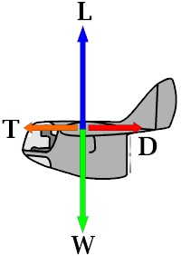
The picture shows what forces are present when flying at cruisespeed ( constant speed, constant height). All forces are compensated. Weight Weight is a constant, ...unless your passenger chooses the safety of a descent by parachute above a landing with your flight-skill. I do not take in count the fuelconsumption. Could be it will be taking in count in a further stage of the theory. Lift At levelflight at a constant speed lift compensates weight. So L = W (formula 1). Main formula for lift is:
Let's simplify this formula. The density of air is 0,3125 kg/m3 (0.0195 lb/cubic ft or 0.52675 lb/cubic yd) at sealevel. So it is a constant at a certain height. Cl does not change at levelflight and at a certain speed. Wingarea is also a constant. What's left? L= constant . v2 (formula 3) So lift is related to the second power of speed. But most important is another relation. If we put formulas 1 and 2 together you see:
Speed needed to keep the airplane in the air is related to the wingloading. Don't make the mistake thinking that this is the stallspeed! For stallspeed you need to look further. This makes that the ultralights for Belgium have a fixed speedrange, because the wingloading is limited by law. Another conclussion could be that unswepted flying wings fly slower than a swepted flying wing. Unswepted flying wings use a reflexed airfoil and these airfoils have a lower Cl. There is more wingarea needed to create the same lift needed to keep the weight in the air. More wingarea for the same weight means lower wingloading. Formula 4 says that then the needed speed gets lower too. Drag Most would think now that if you increase speed all will be well. That would be true if drag did not excist. But it does. Drag has two different components. Parasite drag and induced drag. Parasite drag is the commonly known frictiondrag. Induced drag is more difficult. I have found a explanation that says: "energy lost to create lift is induced drag" ("Composite construction for homebuilt aircraft" by Jack Lambie, Aviation Publishers, Hummelstown, PA, USA). D = Dp + Di (formula 5) I also found in nearly every book the following formulas. Even if you know these formulas, make sure to read further in this dragsection, because some people forget one detail. Dp = 0,5 . Di = W2 / A important relation can be seen between Di
and v. The higher the speed, the smaller the induced drag! Now we introduce
Let's put formula 7 and 8 together. Di = W2 / The higher
Thanks, Don. I didn't know that. Could
somebody quote me the relation between aspect ratio and Cl. I would like to
state it in this section.
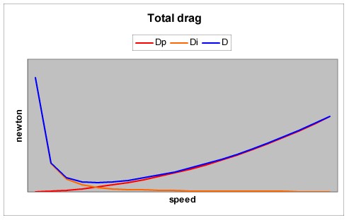
This curve shows that the total drag is the lowest at a certain speed and not at the lowest speed. Here you have two important things to see. In formula 13 you see that the the lift-coefficient is related to the induced drag. If you read the explanation of Jack Lambie about induced drag it isn't hard to understand. The more lift created, the more energy lost, the higher the induced drag.
Secondly you see in formula 12
that CD stands for the parasite drag coefficient of the WHOLE airplane. Many
forget to keep the drag of the fuselage, wheels, struts, tail and so in mind while
designing a model. Here follows a typical conversation with a modelmaker about his first
own design. You have to keep in mind that drag not only works on the wing. It also works on the fuselage. If you work on a ultralight, you will see that the fuselage is rather large in reference to the wing. The frontal area of the fuselagepod can be used to estimate the parasite drag.
In the book "The design of the
aeroplane" of Daroll Stinton I found a table with some crude estimates of some
airplaneparts. A enclosed cockpit of a light airplane with tractorpropeller had a
We hope that you could swallow this chapter before we do mention the factor e or K. The former description of lift is true when using a wing with infinite span. Since we don't have such wings, we need to view the problems which are created at the tip of a wing. What happens? Under the wing you have a positive pressure, above the wing you have a negative pressure. At the tip there is a "leak" of the positive pressure zone towards the negetive pressure zone. This leak creates a vortex (little tornado at the end of the wing). The larger this vortex is, the more energy is lost when creating lift. So Cdi is related to this vortex. Lift is also related to this vortex, because there is little lift in the wing area where the leak passes by. Not all the wingspan creates lift. A certain part of the wing is lost. e is a factor that shows how much of the wing is usefull to create lift. So if e = 0,9 then 10% of the wingspan is lost due to the vortex.
Formula 2 and 13 get transformated into:
As you can see, as e gets less lift gets less, but Cdi gets larger. Thrust T = D (formula 18) I found the following formulas.
You need to know that friction and rotational losses are not included in these formulas. Our classic propellers have in reality a efficiency of 10 to 15% less than the efficienty of the ideal propeller (stated here). Keep this in mind while making estimated calculations! Another thing you need to know is the fact that a airplane not only has to fly level, but it also needs to be able to climb. If two airplane have two same engine and prop, which one is going to climb the best. Well, it is going to be the one with the lowest wingloading. Why? It will have the lowest sinkrate and will need less power to fly level (=at the same height). So all the remaining power can be used to climb. The other airplane with the higher wingloading needs more power to fly level and has less reserve to climb. Once a member of the Nurflugel-mailinglist did ask what power he did need to make his glider self-launching and he have the data of his glider. The glider weighs 180 lbs, and with me its
gross is 330. Al Bowers did answer: "The important ones
are L/D and min sink and weight. Make sure the units are the same (everything is "per
second" and "pounds-force", etc; or do it all SI and remember What Al Bowers didn't mention in the text, but he did use it to get his result, is the fact that the formula (slightly modified) also can be used to get the needed power to not only fly level but to climb as well. Needed power = weight * (minimum sink + climb rate) (formula 21) Be sure to use all the right dimensions.
Weight is Newton (or lbs), minimum sink rate in m/sec (or ft/sec) and climb rate in the
same dimension. Now try to find the data of a motorized glider and see if your
calculations fit with the data of the glider. In the sector "Basic wingdesign" we will show you some other formulas (mainly related to wingform and performance). If you have a problem understanding this section, please state us your question. We will try to search for a possible answer. |
||||||||||||||||||||||||||||||||||||||||||||||||||||||||||||||||||||||||||||||||||||||||||||||||||||||||||||||||||||||||||||||||||||